Kirchhoff’s Laws were published in 1845 by German physicist Gustav Kirchhoff. When Kirchhoff's laws are combined with Ohm's law we are able to calculate voltage and current for complex circuits.
Electric Potential in Circuits
Electric potential roughly represents the concentration of energy in a circuit. The potential quickly spreads to a uniform value throughout an uninterrupted section of wire. This is similar to how water in a cup stays at the same height because it spreads out against the force of gravity.
Differences in electric potential are called voltage.
Electric potential is constant until it reaches a circuit element.
Across a resistor the potential drops, so the voltage is negative.
Across a battery the potential increases, so the voltage is positive.
solution
$$\Delta V = V_f-V_i $$ $$\Delta V = 2\, \mathrm{V}-4\, \mathrm{V}$$ $$\Delta V = -2\, \mathrm{V}$$What is the voltage across the resistor?
solution
Voltage means a potential difference. They are the same.
$$\Delta V = V_f-V_i $$ $$\Delta V = 2\, \mathrm{V}-4\, \mathrm{V}$$ $$\Delta V = -2\, \mathrm{V}$$solution
The potential jumps from 0 to 1.5 V. The battery adds 1.5 volts to the circuit.
solution
$$\Delta V = V_f-V_i $$ $$\Delta V = 0.70\, \mathrm{V}-1.50\, \mathrm{V}$$ $$\Delta V = -0.80\, \mathrm{V}$$$$\Delta V=IR$$ $$R = \frac{\Delta V}{I}$$ $$R = \frac{0.80}{0.0020}$$ $$R = 400 \, \Omega$$
solution
$$\Delta V = V_f-V_i $$ $$\Delta V = 5.5\, \mathrm{V}-9\, \mathrm{V}$$The current is to the left, because the potential is dropping from right to left and resistors always decrease voltage.
answer
The current is directed to the left. Current is the flow of charge, and charge flows from high potential to low potential.
Question: Which path has the highest current? Why?
answer
The 100 Ω resistor has the highest current
All three paths have the same voltage, so the only difference is the resistance. Resistance makes it harder for current to flow. The lowest resistor will have the highest current.
Example: Calculate the current across each resistor.
solution
$$\Delta V = IR$$ $$I = \frac{\Delta V}{R}$$ $$I = \frac{1.5 \, \mathrm{V}}{400 \, \Omega} \quad \enspace \quad I = \frac{1.5 \, \mathrm{V}}{200 \, \Omega} \quad \enspace \quad I = \frac{1.5 \, \mathrm{V}}{100 \, \Omega}$$ $$I = 0.00375 \, \mathrm{A} \quad \quad I = 0.0075 \, \mathrm{A} \quad \quad I = 0.015 \, \mathrm{A} $$ $$I = 3.75 \, \mathrm{mA} \quad \quad I = 7.5 \, \mathrm{mA} \quad \quad I = 15 \, \mathrm{mA} $$solution
Subtract the potential before and after each element to find potential difference across each element.
$$V_f-V_i = \Delta V $$ $$2\, \mathrm{V}-6\, \mathrm{V} = -4\, \mathrm{V}$$ $$0\, \mathrm{V}-2\, \mathrm{V} = -2\, \mathrm{V}$$ $$6\, \mathrm{V}-0\, \mathrm{V} = 6\, \mathrm{V}$$You might have noticed that the total voltage for either path the current could take adds up to zero. This is an important principle.
$$+6 \, \mathrm{V} -4 \, \mathrm{V} -2 \, \mathrm{V} = 0$$Kirchhoff’s Law: Voltage
If it is possible for the current to take a looping path through the circuit, the total change in potential is zero. Otherwise the potential would keep getting higher.
For any closed circuit loop the sum of all voltages equals zero.
$$ \sum V = 0 $$ $$ V_1+V_2+V_3+V_4 = 0 $$
\(V\) = potential difference, voltage [V, volts]Kirchhoff's Voltage law is a consequence of conservation of energy. Voltage is electric potential energy per charge. As current flows through the circuit, total energy doesn't change.
hint
The total voltage for any looping path must add up to zero.
$$ V_1+V_2+V_3+V_4 = 0 $$solution
$$ V_1+V_2+V_3+V_4 = 0 $$ $$ 1.51-0.55-0.33-V_{4} = 0 $$ $$ V_{4} = -0.63\, \mathrm{V} $$solution
All elements in a series have the same current
$$V = IR$$ $$V = (0.000194)(6000)$$ $$V = 1.164\, \mathrm{V}$$$$V = IR$$ $$V = (0.000194)(20000)$$ $$V = 3.88\, \mathrm{V}$$
$$V = IR$$ $$V = (0.000194)(5000)$$ $$V = 0.97\, \mathrm{V}$$
Use the resistor voltages to calculate the voltage in the battery.
solution
$$ \sum V = 0$$ $$ V_{bat}+V_1+V_2+V_3 = 0 $$ $$ V_{bat} = -V_1-V_2-V_3 $$ $$ V_{bat} = 1.164+3.88+0.97 $$ $$ V_{4} = 6.014\, \mathrm{V} $$solution
Only one of the 3.4V drops are in each loop.
$$ \sum V = 0$$ $$ 9 - 3.4 - V = 0 $$ $$V = 5.6 \, \mathrm{V}$$$$V=IR$$ $$R = \frac{V}{I}$$ $$R = \frac{5.6}{0.0005}$$ $$R=11200 \, \Omega$$
Kirchhoff’s Law: Current
Kirchhoff’s current law is true because charge is conserved. Total charge can't increase or decrease.
At any point on a circuit, the total charge flowing in equals the total charge flowing out.
$$ I _{in} = I_{out} $$
\(I_{in}\) = charge entering a point per second [A, amps]\(I_{out}\) = charge exiting a point per second [A, amps]
Sections of a circuit that don't branch will have the same current everywhere.
solution
$$ I _{\text{in}} = I_{\text{out}} $$ $$ 2\, \mathrm{A} + 2\, \mathrm{A} = I_{\text{out}} $$ $$ 4\, \mathrm{A} = I_{\text{out}} $$solution
The total current entering a part of a circuit must equal the total current exiting. If a circuit doesn't branch it will have the same current at every point. Current doesn't change across resistors and batteries.
solution
no need to convert units for just addition and subtraction
$$ I _{\text{in}} = I_{\text{out}} $$ $$ I _{\text{in}} = 20\, \mathrm{mA} + 40\, \mathrm{mA} + 55\, \mathrm{mA} $$ $$ I _{\text{in}} = 115 \, \mathrm{mA} $$solution
$$ I _{\text{in}} = I_{\text{out}} $$ $$ 450\, \mathrm{mA} = I_{1} + 115\, \mathrm{mA} + 120\, \mathrm{mA} $$ $$450\, \mathrm{mA} - 115\, \mathrm{mA} - 120\, \mathrm{mA} = I_{1}$$ $$ 215 \, \mathrm{mA} = I_{1}$$Resistors in Series
Electrical components are in a series when they are connected in a single path so that all charge flows through the same components.
The total equivalent resistance for resistors in a series is the sum of the resistors.
$$R_{eq} = R_1+R_2+R_3+\cdots$$
\(R_{n}\) = A single resistor in a series [ohms, Ω]\(R_{eq}\) = Equivalent resistance. The resistance of a single resistor that could replace several resistors. [ohms, Ω]
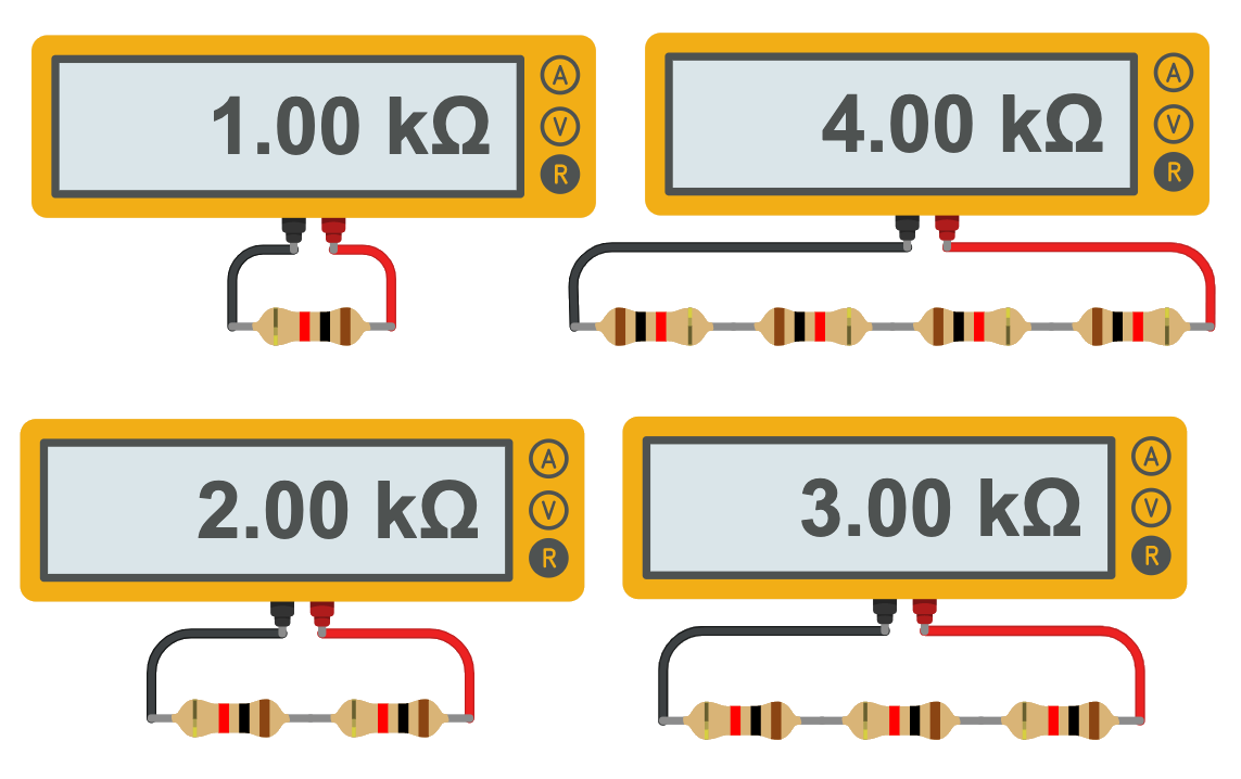 Adding resistors in series increases the total resistance.
solution
$$R_{eq} = R_1+R_2+R_3+R_4$$ $$R_{eq} = 120\, \Omega + 150\, \Omega + 200\, \Omega + 100\, \Omega$$ $$R_{eq} = 570\, \Omega$$Resistors in Parallel
Electrical components are in parallel when the path branches, and charges take different paths. The equation for replacing resistors in parallel is a bit more complex.
The inverse of the total equivalent resistance for resistors in parallel is equal to the sum of the inverse of each resistance.
$$\frac{1}{R_{eq}} = \frac{1}{R_{1}}+\frac{1}{R_{2}}+ \frac{1}{R_{3}}+\cdots$$
\(R_{n}\) = A single resistor in parallel [ohms, Ω]\(R_{eq}\) = Equivalent resistance. The resistance of a single resistor that could replace several resistors [ohms, Ω]
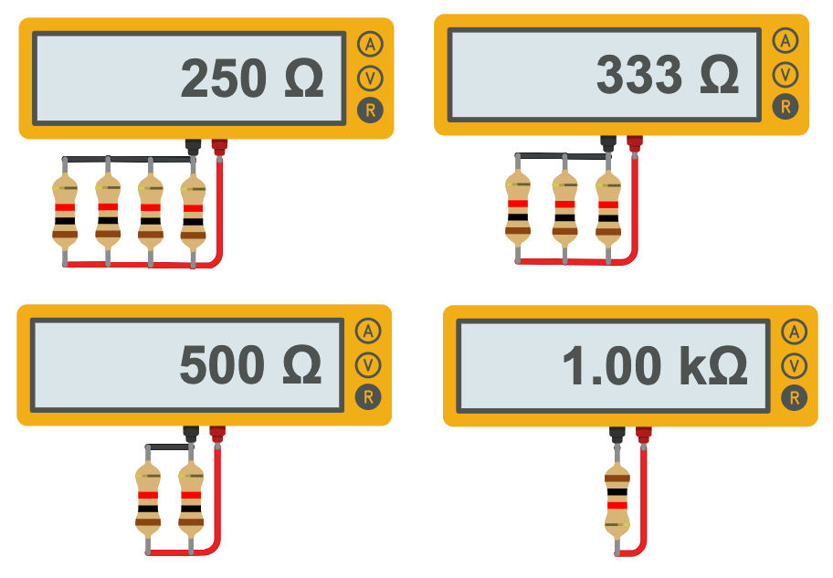 Adding resistors in parallel lowers the total resistance.
This makes sense if you think of each parallel resistor as a possible path for current.
More paths allow more current and less total resistance.
Adding resistors in parallel lowers the total resistance.
This makes sense if you think of each parallel resistor as a possible path for current.
More paths allow more current and less total resistance.
solution
$$\frac{1}{R_{eq}} = \frac{1}{R_{1}} + \frac{1}{R_{2}} + \frac{1}{R_{3}} + \frac{1}{R_{4}} + \frac{1}{R_{5}}$$ $$\frac{1}{R_{eq}} = \frac{1}{100} + \frac{1}{100} + \frac{1}{100} + \frac{1}{100} + \frac{1}{100}$$ $$\frac{1}{R_{eq}} = \frac{5}{100}$$ $$R_{eq} = \frac{100}{5}$$ $$R_{eq} = 20 \, \Omega$$solution
$$\frac{1}{R_{eq}} = \frac{1}{R_{1}} + \frac{1}{R_{2}} + \frac{1}{R_{3}}$$ $$\frac{1}{R_{eq}} = \frac{1}{400} + \frac{1}{200} + \frac{1}{100}$$ $$\frac{1}{R_{eq}} = \frac{1}{400} + \left(\frac{2}{2}\right)\frac{1}{200} + \left(\frac{4}{4}\right)\frac{1}{100}$$ $$\frac{1}{R_{eq}} = \frac{1}{400} + \frac{2}{400} + \frac{4}{400}$$ $$\frac{1}{R_{eq}} = \frac{7}{400}$$ $$R_{eq} =\frac{400}{7}$$ $$R_{eq} = 57.14 \, \Omega$$solution
$$\frac{1}{R_{eq}} = \frac{1}{R_{1}} + \frac{1}{R_{2}}$$ $$\frac{1}{10} = \frac{1}{30} + \frac{1}{R_{2}}$$ $$\frac{1}{10} - \frac{1}{30} = \frac{1}{R_{2}}$$ $$\frac{3}{30} - \frac{1}{30} = \frac{1}{R_{2}}$$ $$\frac{2}{30} = \frac{1}{R_{2}}$$ $$15\, \mathrm{k} \Omega = R_{2}$$(Start with the highlighted resistors in series.)
solution
$$ \text{Equivalent Resistance} = 266.6 \, \Omega $$Solving Complex Circuits
How do you solve a circuit with both series and parallel elements? One technique is to simplify the circuit by replacing resistors in series or parallel with one equivalent resistor.
finding resistance for a simplified circuit
We can start by combining the two parallel resistors.
$$\frac{1}{R_{eq}} = \frac{1}{R_{2}} + \frac{1}{R_{3}}$$ $$R_{eq} = \left(\frac{1}{800} + \frac{1}{900}\right)^{-1}$$ $$R_{eq} = \left(0.00125 + 0.00\overline{11}\right)^{-1}$$ $$R_{eq} = 420 \, \Omega$$Next we can combine the 3 resistors in series.
$$R_{eq} = 600+420+500$$ $$R_{eq} = 1520 \, \Omega$$using Kirchoff's laws to build back up to the full circuit
Kirchoff's Voltage law says that the total positive voltage must equal the negative voltage. This tells us the voltage drop on the resistor is the same as the battery.
$$V_{bat} + V_1 = 0$$ $$6.0 \, \mathrm{V}+ V_1 = 0$$ $$V_1 = -6.0 \, \mathrm{V}$$We can solve for current through the resistor with Ohm's law.
$$V=IR$$ $$I = \frac{V}{R}$$ $$I = \frac{6.0\, \mathrm{V}}{1520\, \Omega}$$ $$I = 0.0039\, \mathrm{A}$$This current can be applied to any circuit element in series with Req. If we expand the circuit back to when they were all in a series we will know the current for all the resistors.
We can use Ohm's law to find voltages.
Resistors in parallel have the same voltage, but not the same current. Let's expand back to our full size circuit and fill in the voltage.
We can use Ohm's law on R2 and R3 to find current.
solving for power dissipated
We can calculate the power dissipated by each element.
checking our work
That was a long problem. Let's check our work. The total voltage should equal zero, if we count the resistors in parallel as one.
$$V_1+V_4+V_{eq} + V_{bat} = 0$$ $$-2.3-2.0-1.7+6.0 = 0 $$ $$0 = 0 $$The power from the battery should equal the sum of the power lost in the resistors.
$$P_{bat}=IV$$ $$P_{bat}=(0.0039)(6.0)$$ $$P_{bat}=0.023\, \mathrm{W}$$$$P_{res} = 0.0090\, \mathrm{W}+0.0078\, \mathrm{W}+0.0036\, \mathrm{W}+0.0032\, \mathrm{W}$$ $$P_{res} = 0.023\, \mathrm{W}$$
Looks good!
strategy
Replace the three resistors in parallel with one equivalent resistor. The equivalent resistor will have the same voltage as each resistor in parallel because of Kirchhoff's voltage law.
Use Ohm's law to find the current through the equivalent resistor. That will be the same current that flows through the 30 kΩ resistor. We will then be able to find the voltage in that resistor with Ohm's law.
The battery's voltage is equal to the sum of the voltages across each resistor because of Kirchoff's voltage law.
solution
Voltage is the same in parallel. The equivalent resistance has 3.0 V because the 80 kΩ resistor has 3.0 V.
The current in a series is the same, so we also know the current in the 30 kΩ resistor. With current and resistance we can calculate the voltage too.
$$V=IR$$ $$V=(0.000104 \, \mathrm{A})(30\,000 \, \Omega)$$ $$V= {\color{#0a7}3.125 \, \mathrm{V}}$$We can use Kirchhoff’s voltage law to find the voltage in the battery.
$$0=V_{\mathrm{bat}} + V_1 + V_2$$ $$V_{\mathrm{bat}} = -V_1 - V_2$$ $$V_{\mathrm{bat}} = 3.0 \, \mathrm{V} + 3.125 \, \mathrm{V}$$ $$V_{\mathrm{bat}} = {\color{#c09} 6.125 \, \mathrm{V}} $$